WEEK 6 Electronic design
- Eagle
- circuit board
- soldering
Eagle
1. download Eagle first, it is a free software from autodesk.2. find a toturial for Eagle. here is a highly recommand useful series toturial for starting.Evert part of vedio is limit in 5 minutes, for efficient learning.
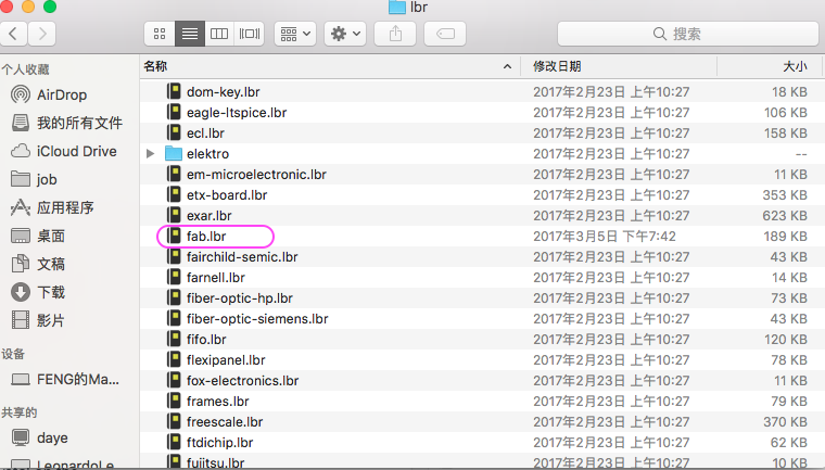
3. download the fab.lbr library for add electrical components for this week assignment. and then add it into Eagle lab
Draw schematic
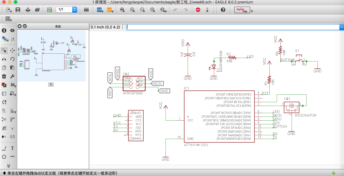
1.start to draw the schematic. the reason is the link in the toturial for hello.fdti.44 schematic invalid, so i decide to draw the whole schematic according to the image offer on the toturial page.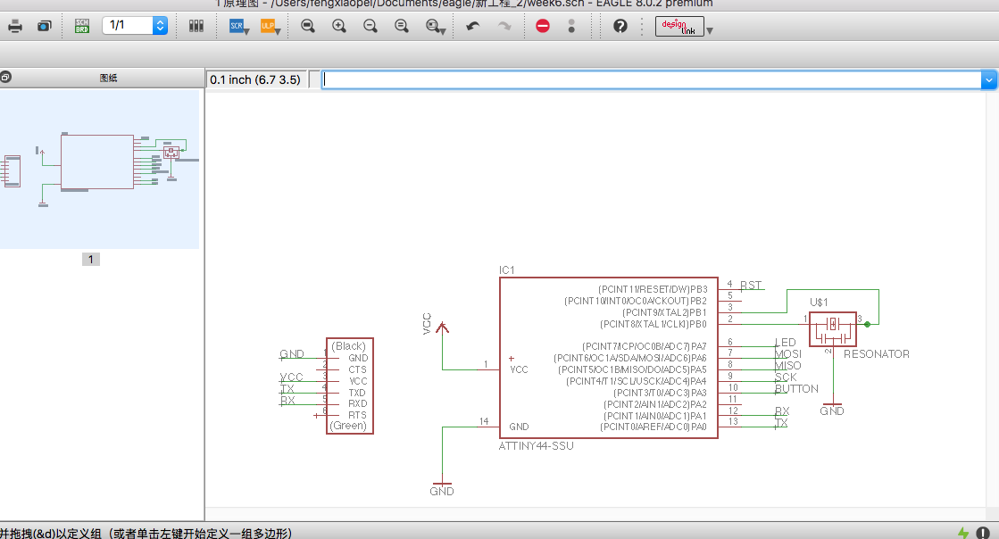
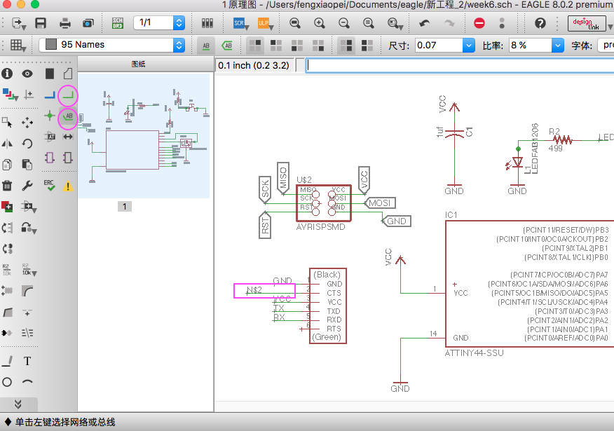
2. draw a line extention from pin of component and lable it.
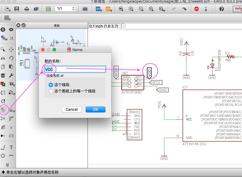
3. as show in below image , change name for the component.
4. when switch to the Board Layout use the button
, we can see the the arrangement of the component is mess up together
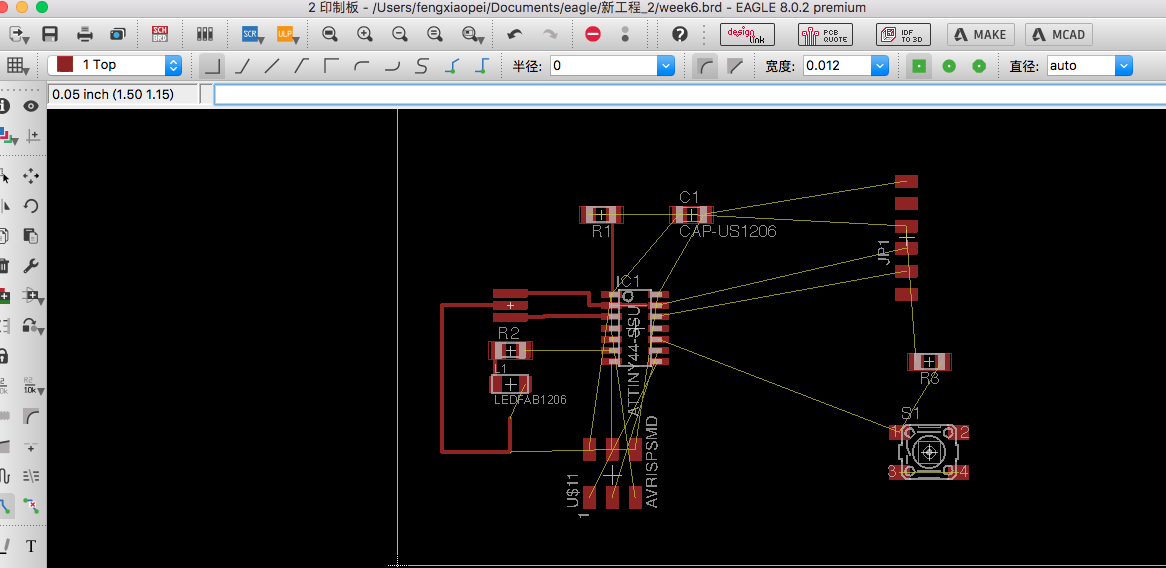
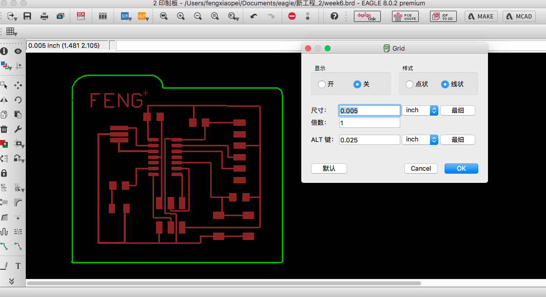
5. set the grid line to 0.005 inch , to make much more easier for route circuit line.
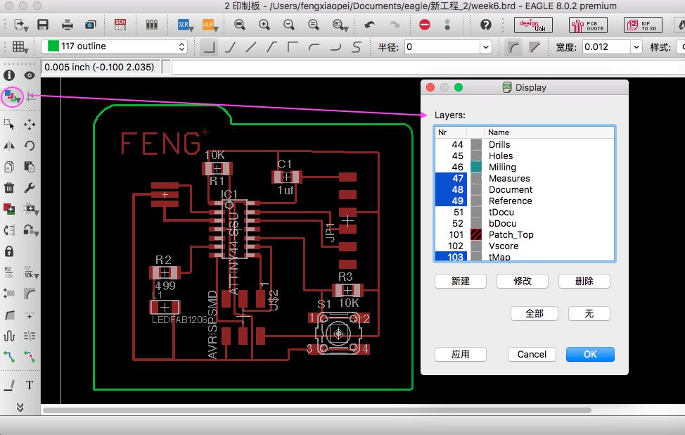
6. when finish route line, use the layers to select display layer for export.
7. set different color to make outline(green) of the circuit board for later expot to png image.
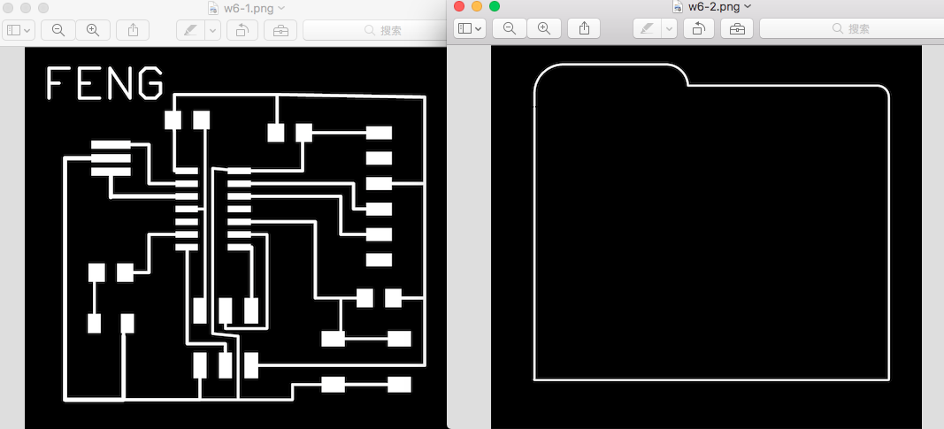
8. export to png image, and then go to fab modules to convert file type for Roland mill.
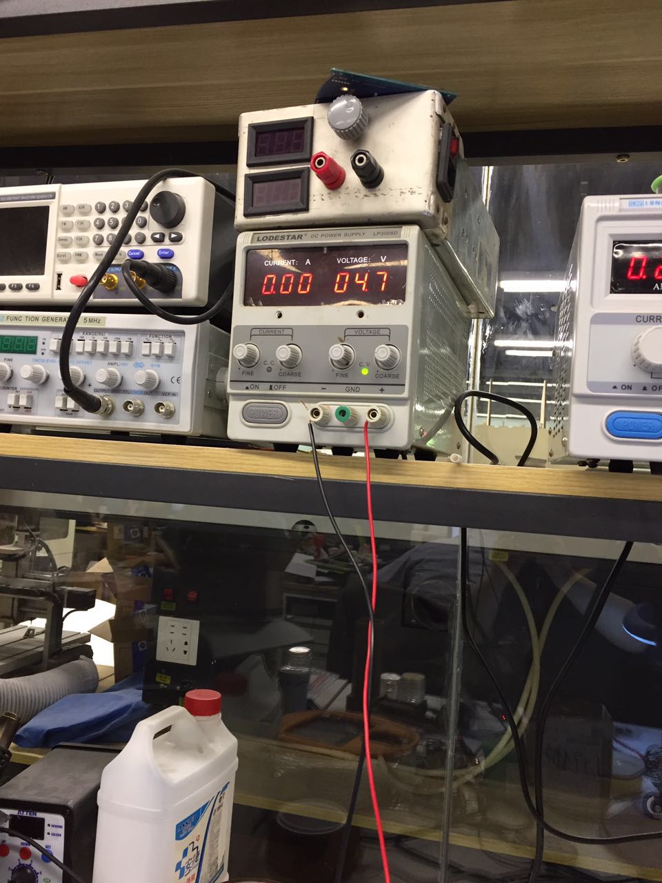
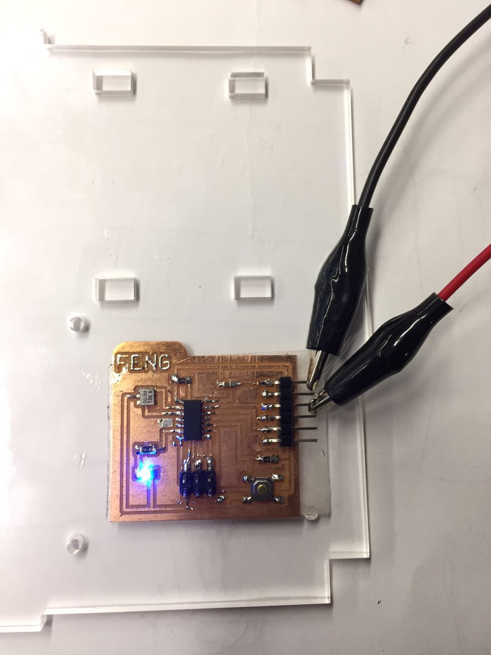
9.mill the board like week 4. then sold all component on board, get charge for board, lighten LED